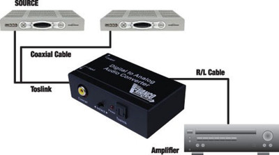
In order to change the voltage or current of a power supply, the reference can be changed. Most microcontrollers are too slow to be a part of a power supply control loop. In order to play back this audio, a DAC is used to convert it into a sound signal that can be played back on a speaker.

The audio is converted to binary after which operations can be performed on it.

It is much easier to work with signals once they have been converted to binary.Ī good example of this is audio editing. The voltage output is proportional to the duty cycle of the input – the higher the duty cycle the greater the output voltage of the filter. However, this is intended to be used with a RC filter to convert the PWM signal into a voltage value by filtering out the AC component and leaving behind the DC component. On the outset the PWM signal looks like a binary waveform with only high and low peaks with a variable duty cycle (ratio of on time to time period). The popular Arduino microcontroller has the capability to output analog signals using a PWM signal. This is the type of DAC that most of us have used without even knowing it! The binary input goes into the 2R resistors and the output is obtained at the bottom of the ladder. You can think of this as a somewhat complex voltage divider, though the math is quite complex. This is the simplest type of DAC and needs only two resistor values arranged in a ladder. The limitations can be overcome by using the next method. The more bits you have, the more different values of resistors you need – and this is not always practical. What makes this circuit work is the resistors – each resistor has to be carefully chosen and matched in order to obtain an accurate analog output. The binary input goes into the resistors and the analog output is obtained on the output of the op-amp. The junction where the resistors meet is called the summing junction or the virtual ground.

This is basically an op-amp amplifier with multiple resistors connected to one input. Since digital to analog conversion is simply a weighted sum of the binary input, a circuit called a summing amplifier is used. In other words the whole digital to analog conversion process can be thought of as a scaling operation – the binary count is mapped to a certain voltage range, with 0V being the minimum and the maximum voltage being the maximum input binary voltage. a place value system, with each bit representing the presence or absence of a certain power of two in the total sum of the powers. The binary system is a positional system, i.e. So here, we will a DAC to convert the digital audio file to analog signal in order to play it on a speaker.

In order to play these back as sound on a speaker we need analog signals, because as we know the speaker’s diaphragm vibrates based on the intensity of the analog signal to produce sound/music. In this article we will learn how a DAC works and how it can be used in out designs.Ī computer is a binary machine operating in an analog world, so to be able to produce an output that is understandable by other devices a DAC is used.įor example, a computer stores audio in the form of binary values of the sound wave. There are many techniques in which this is done, each with its own advantage and disadvantage. In this article we will learn how Digital signals can be converted to Analog voltages using DACs.Ī Digital to Analog Converter commonly referred as DAC, D/A or D2A is a device that converts binary values (0s and 1s) to a set of continuous analog voltages. We already learnt how Analog to Digital Converters (ADC) is used to convert analog signals to digital value. In a typical electronics design, these two signals often have to be converted from one form to another. All Digital Electronics like Logic Gates, Flip-Flops, Microcontroller, Microprocessor etc work with Digital Signals, while the Analog Electronics like Op-Amp, Power switches etc. When talking about signals, they can be broadly classified into analog signals and digital signals.


 0 kommentar(er)
